Annotation helps to make a 3D model more accessible for use with instruction. Annotation can take on a number of forms such as labeling axes, including the equation of the function(s) which generated the object, the course the object is for, etc.
The following is a simple set of tutorials for annotating a 3D model with text.
Raised Lettering:
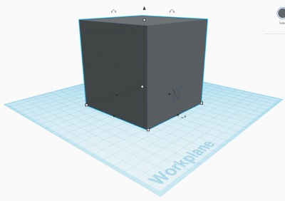
- Create a new model in TinkerCad.
- Using “Basic Shapes”, create a new “Box” shape of 80x80x80mm.
- Switch to from “Basic Shapes” to “Text and numbers”
- Create a new Text object of the letter “X” with a thickness of 2mm. (Do not create the letter “X” directly as an object.)
- Rotate the letter “X” around the ‘x’ axis by π/2.
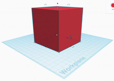
- Position the letter “X” in the x/y plane so that it is in the middle of the face of the “Box” along the ‘x’ axis, and sticking 1mm into the box.
- Grab the ‘vertical translation’ handle of the letter ‘X’ and move it to the center of the face of the “Box”.
- Shift click on the “Box” and click the “Group” operation.
- The object is now a composite object consisting of union of the “Box” annotated with the letter “X”; and can be moved/rotated as a single object. The letter “X” is raised on the surface of the box.
Inset lettering:
- Select the composite object and click on the “UnGroup” operation. This separates the object into its original constituent objects.
- Click on the letter “X” and select “Hole” in the “Shape” attributes. This turns the letter “X” into a “hole” instead of a solid.
- Shift click on the “Box” and click on the “Group” operation.
- The object is now a composite object consisting of difference of the “Box” annotated with the letter “X”; and can be moved/rotated as a single object. The letter “X” is now inset into the box.
Annotation on other planes may be accomplished in a similar way.
Advanced annotation tutorials:
Labeling all Axes
- Ungroup the composite object and set the letter “X” attribute to “Solid”.
- Rotate the letter “X” back into the X-Y plane and translate it vertically to be at “Z=0”.
- Add a new “Box” object with the size 20x5x2mm.
- Add a new “Roof” object. Rotate and transform (Scale, Rotate, Translate) the “Roof” so that it forms an “Arrow” with the new “Box” and group them together.
- Translate the “Arrow” so that it is in a good position relative to the letter “X”, and group it with the letter “X” to form an “X Axis” label.
- Duplicate the composite object and position it clear of the original.
- Ungroup the duplicate object, and change the letter “X” to the letter “Y” then regroup the components of the object to form the “Y Axis” label..
- Position the “Y Axis” label on the Y-Z face of the cube.
- Duplicate the “X Axis” label again and change the letter to “Z” to form a “Z Axis” label.
- Position the “Z Axis” label on the Y-Z plane and rotate it so the arrow is pointing up and it is not crowding the “Y Axis” label.
- Position the “X Axis” label on the “X/Z” face of the “Box”.
- Make sure that the axis labels for a “right-handed” coordinate system, unless a “left-handed” coordinate system is desired.
- Group the “Box” and axis labels together into a composite box. The box is now annotated on all three coordinate axes.
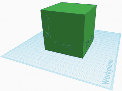
TinkerCad Axis Annotation Model
Labeling a Mobius Strip:
Labeling text on a Mobius strip a bit more complicated. The general surface is curved, and the surface is non-orientable.
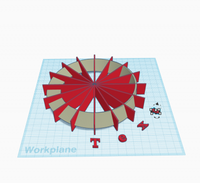
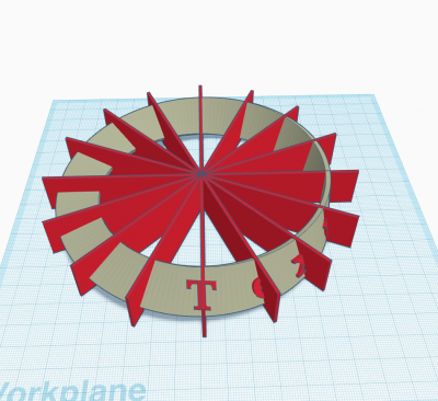
- The first step in labeling text is to create a temporary set of spokes to provide some angular reference when transforming letters of the text, usually 10 spokes are sufficient.
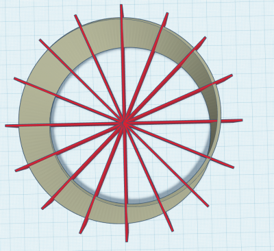
- Create the individual letters of the text in the XY plane, position them along the spokes, and rotate them in the orientation of the spoke.
- Select a letter and position it along the Mobius strip so that it is in the plane of the gradient at the location the letter is to be placed, and the letter is sticking out of the mobius strip by approximately 2mm, while also being embedded in the Mobius strip. Note that this takes practice, and make sure that the letters are not protruding through the back side of the Mobius strip.
- The final step is to remove the temporary spokes.
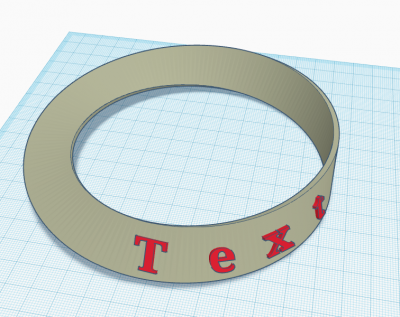
- Annotation can be applied along ALL of the surface from 0 to 4π. Keeping the orientation of the letters while traversing the surface is the only challenging issue.